I'm working on one OSD firmware and I needed couple more flight controllers to test it with, so I decided to get few cheap and few not cheap FCs. Problem with the cheap ones is the lack of documentation, only few snippets here and there. I decided to identify all the pins I spend some time measuring things, looking at the board with microscope and looking at the datasheets and I identified all the pins and functions on the board. Concluded into one single high-res image, input and output ports are described in Atmel syntax and in Arduino syntax as well.

Quick facts (I wish they were condensed somewhere before I was buying this board):
- MultiWii v3 board is actually Flip EZ clone and lot of information about Flip EZ will apply to this board (even it's easier to search for Flip EZ specs than for MWv3)
- Front of the board is labeled with big white arrow with power LED inside it.
- Uses Atmel Mega 328P chip, to flash it from Arduino IDE you need to select Arduino Duemilanove Atmel328P 5V 16Mhz
- From above the board runs 5V and 16Mhz so other components connecting to it should run same voltage or use level shifters
- Inside the MultiWii software in config.h you need to uncomment the #define FLYDUINO_MPU line as this FC is identified in MW as flyduino
- For the USB comunication it uses SiLabs CP2102 chip and tested it on Windows / Linux (the CP210x driver works fine). Be careful: USB communication shares same pins as serial port, you will get into problems if you will have both of them plugged in at the same time.
- For stabilization it uses 6 axis accelerometer + gyroscope sensor, but is lacking compass, baroscope and magnetometer.
- 1x I2C port, you should be able to connect GPS and other sensors with it, should support multiple nodes on bus (for some GPS functionality you will need functional compass).
- 1x Serial port, you should be able to connect Bluetooth but I personally tested only OSD (only 1 node on this bus is possible and it's even shared with USB do plug both of them at the same time)
- The board has tiny ISP connector to flash firmware directly (in the image is described what pins mean what). It's much smaller than regular ISP connectors so you will need to make dedicated connector for it.
- Input and output pins use standard servo pinout (signal, + voltage, ground). The + voltage in the image is called Vin and is separated from the rest of the board (more details about it below)
- Input chanels are in this order: Throttle, Roll / Ailerons, Pitch / Elevator, Yaw, Aux1 and Aux2
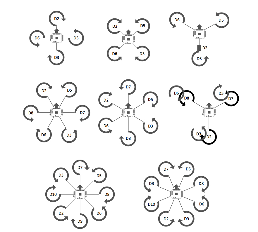
- For output channels easiest way is to flash it with MultiWii in desired configuration (tricopter quadrocopter etc...) and then connect into MultiWii GUI to see what output channels are used. Have a look to reference image on the bottom.
- There 4 more pins D8, A3, A6, A7 which are located on the corner of the board.
- Board has two different voltages Vin and VCC. VCC is basically used by whole board and Vin is used with the servo connectors.
- I seen other people struggle with this so it could be helpful to people. To power the board from the servo pins with Vin there is SOT 25 sized chip labeled LB50 which is MIC 5205 LDO low dropout 5V linear voltage regulator. Close to it are 3 pins, labeled them VLR, VCC and Vin. The voltage from Vin is feed into the 5V linear regulator and output is what I called VLR. This allows you to do following 3 things with the board:
- Have separate voltages on board, do not connect pins and you can have separate voltage on servo connectors and separate voltage on USB, serial and I2C ports.
- Bridge VCC and Vin with solder to power directly the board from voltage coming from input/output servo connectors. If you now have something like BEC connected on the output ports and power whole board with it, now you need to be careful not to connect USB at the same time (if you need to connect USB, just power down BEC first)
- Bridge VCC and VLR to have the Vin stabilized down to 5V before powering the board, this is for cases where the input/output servo connectors have higher voltage than 5V. Again be careful not to connect any other power source like USB described above.